
Understanding Arc Flash Hazards and Incident Energy Goals
To choose the right arc flash mitigation solutions, you first have to understand what happens during an arc flash event. When an arcing fault occurs, current flows through the air between ungrounded phase conductors, or between a phase conductor and ground. This ionized gas path turns the surrounding atmosphere into a conducting plasma channel, releasing massive thermal energy in microseconds.
Thermal radiation from an electrical arc can reach temperatures exceeding 35,000°F—hotter than the surface of the sun. This intense thermal output vaporizes copper and aluminum busbars instantly. The metallic vapor expands to thousands of times its original volume, generating a mechanical blast pressure wave capable of throwing workers across rooms, rupturing switchgear cabinets, and showering work areas with molten shrapnel.
Causes and Impacts of Arc Flash Events
Arc flashes rarely happen without a trigger. Dust accumulation, moisture buildup, foreign objects (like a dropped hand tool), rodent infestation, or insulation breakdown can bridges phase conductors. Human error during maintenance or troubleshooting remains one of the primary triggers.
In low-voltage industrial systems—particularly 480V installations—arcing faults present a counterintuitive danger. Because air impedance restricts arcing fault current, the current level often drops to 45–50% of the maximum 3-phase bolted fault current. Standard inverse time-current curve (TCC) protective devices like circuit breakers or fuses may interpret this lower current as a standard overload rather than a severe fault.
As a result, clearing times balloon from milliseconds into full seconds. A 480V fault with lower arcing current can yield higher total incident energy than a higher-voltage fault that clears instantly. Watching out for 5 Warning Signs Your Commercial Electrical System Needs Immediate Attention helps identify deteriorating equipment before catastrophic failure occurs.
Primary Goals of Hazard Reduction
The primary objective of implementing arc flash mitigation solutions is to reduce the incident energy—measured in calories per square centimeter (cal/cm²)—at a specific working distance.
Targeting incident energy levels below 1.2 cal/cm² keeps potential thermal exposure at or below the threshold for second-degree burns on bare skin. Lowering incident energy yields several key operational benefits:
- PPE Category Reduction: Workers can operate in lightweight, standard flame-resistant (FR) daily workwear rather than bulky Category 4 arc flash suits (40 cal/cm² rated), improving mobility and reducing heat stress.
- Faster Clearing Times: Shortening the fault clearing time directly cuts the energy transferred into electrical enclosures.
- Minimized Operational Downtime: Lower incident energy limits damage to the arc footpoint, allowing facilities to restore power within hours rather than waiting weeks for total switchgear replacement.
- Enhanced Business Continuity: Protecting electrical assets safeguards ongoing plant operations and eliminates revenue loss caused by unscheduled outages.
The Three Primary Categories of Arc Flash Mitigation Solutions

A balanced safety program relies on a hierarchy of risk controls. The three primary categories of mitigation include modifying work practices, retrofitting existing controls, and installing modern equipment.
Implementing Work Practice Changes as Arc Flash Mitigation Solutions
Administrative controls and modified work practices represent the first line of defense:
- De-Energized Work Policies: Whenever possible, establish an electrically safe work condition prior to starting work.
- Sequence of Operation Protocols: Mandate remote switching procedures so technicians avoid standing in front of energized panels during breaker racking or switching.
- Enhanced Lockout/Tagout (LOTO): Integrate mandatory multi-step voltage verification into routine maintenance routines.
- Targeted Safety Training: Conduct safety awareness training for both qualified electrical personnel and non-electrical facility employees.
Retrofitting Existing Equipment with Engineering Controls
When de-energizing is impossible, retrofitting legacy distribution gear with engineering controls cuts clearing times:
- Maintenance Switches: Installing an Arcflash reduction maintenance system gives technicians a dedicated, instantaneous trip circuit that bypasses normal selective delay during active servicing. This reduces fault clearing time by approximately 20 ms compared to standard digital instantaneous protection.
- Zone Selective Interlocking (ZSI): Hardwired or networked communication between protective trip units lets upstream breakers bypass their intentional time delay when a fault occurs directly on their bus zone, clearing the fault rapidly.
- Upgrading Legacy Components: Replacing electromechanical relays with digital microprocessor relays accelerates fault processing. If your building features outdated panels, review Why You Should Upgrade Old Electrical Outlets and Switches to improve overall system safety.
Installing Advanced New Switchgear and Equipment
For new construction or complete equipment overhauls, installing modern arc-resistant switchgear offers built-in structural containment. Tested under standards like IEEE C37.20.7, arc-resistant gear features reinforced enclosures, ruggedized doors, pressure-relief vents, and internal compartmentalization designed to redirect explosive blast gases upward and away from surrounding technicians.
Active Arc Detection, Quenching, and Clearing Systems
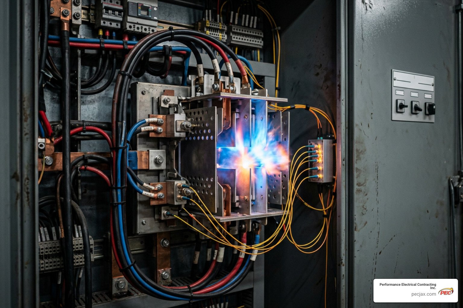
Active mitigation technologies detect the physical characteristics of an arc fault as it forms and take action to clear or extinguish it in milliseconds.
Optical and Light-Sensing Relays
Optical arc protection relies on high-speed light sensors installed inside switchgear compartments. These point light sensors or flexible continuous fiber-optic loops sense the intense flash emitted during the initiation phase of an arcing fault.
Systems like the Arc Guard System™ – TVOC-2 and CSU-2 transmit an optical signal to a central relay in under 1 ms. Integrating these relays with ultra-fast circuit breakers yields total arc fault clearing times around 50 ms.
Other systems, such as Varixx ZYGGOT® ARC V5F technology, target ultraviolet (UV) radiation released before visible light appears, achieving action times under 0.3 ms (300 µs).
To prevent nuisance trips caused by camera flashes, sunlight, or ambient lighting, optical relays use dual-conditioning trip logic. The relay requires both light detection and an overcurrent threshold trigger from current transformers before issuing a trip command.
Arc Quenching Switchgear and Active Pyrotechnic Mitigation
Arc quenching switchgear takes active mitigation a step further by neutralizing the arc fault without waiting for an upstream circuit breaker to open.
When optical sensors detect a fault, an active quenching system—such as the Magnum DS Arc Quenching Switchgear | Eaton—fires a pyrotechnic actuator or high-speed drive. This mechanism closes a low-impedance copper bus pathway, creating a controlled 3-phase short circuit upstream of the fault.
By transferring the energy into this sealed internal shorting path, the arc fault loses its voltage driving force and extinguishes in under 4 ms. Systems like the ARCON Arc Fault Protection System | Overview | Eaton achieve full arc mitigation in 2 ms or less, keeping incident energy below 1.2 cal/cm².
Active Technologies vs. Arc-Resistant Equipment
| Feature | Arc-Resistant Switchgear | Active Arc Quenching / Relays |
|---|---|---|
| Primary Protection Mechanism | Physical containment & blast redirection | Sub-4ms energy interruption / shorting |
| Open-Door Maintenance Protection | None (protection requires doors fully sealed) | Full protection during open-panel work |
| Equipment Damage Post-Fault | Moderate to severe localized damage | Minimal (confined to initial footpoint) |
| Footprint & Room Requirements | Larger footprint; requires high ceilings/ducts | Standard switchgear footprint; no exhaust ducts |
| Total System Clearing Time | Typically 50 ms – 200 ms (breaker-dependent) | Extremely fast (<2 ms to 4 ms quenching) |
Passive Safety Hardware and Engineering Controls
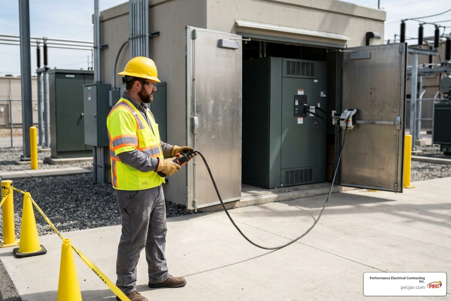
Passive engineering controls reduce worker exposure by creating physical distance or eliminating open-door maintenance tasks.
Remote Racking and Thermal Inspection Hardware
Distance remains one of the simplest ways to protect personnel. Because incident energy drops with the square of the distance, keeping operators outside the arc flash boundary significantly lowers risk.
- Remote Racking Systems: Motorized, remotely controlled actuators attach to circuit breakers, allowing technicians to rack low- or medium-voltage breakers in or out from behind a safety barrier outside the arc flash boundary.
- Remote Switch Actuators: Portable battery-powered actuators mount externally over switch handles via magnetic mounts, letting personnel operate switches from up to 30 feet away.
- Infrared (IR) Windows: Permanently installed transmissive IR windows let thermographers perform routine thermal imaging scans on energized busbars without opening switchgear cabinet doors, removing exposure to live conductors.
Evaluating Permanent Devices as Arc Flash Mitigation Solutions
Permanent Electrical Safety Devices (PESDs) enhance standard LOTO procedures. High-impedance voltage verification test ports and permanently mounted LED voltage indicators allow technicians to verify the presence or absence of voltage using a multimeter without opening enclosure doors. Combining PESDs into daily LOTO routines reduces open-cabinet exposure. As electrical loads expand, reviewing The Importance of Electrical Capacity Planning for Growing Homes and Businesses ensures your service equipment can support modern safety retrofits.
Compliance Standards, Risk Assessments, and System Coordination
Implementing arc flash mitigation solutions requires adherence to established safety standards and engineering frameworks:
- NFPA 70E: Standard for Electrical Safety in the Workplace (mandates risk assessments, LOTO procedures, safe boundaries, and PPE requirements).
- IEEE 1584: Guide for Performing Arc-Flash Hazard Calculations (provides the mathematical equations used to calculate arcing current, incident energy, and boundaries).
- NEC 240.87: Arc Energy Reduction requirements for circuit breakers rated or adjustable to 1200A or higher.
Conducting Arc Flash Analysis and Equipment Labeling
An arc flash study begins with an engineering analysis of the facility’s power distribution network. Engineers map short-circuit currents, protective device clearing times, and device settings to calculate incident energy levels across switchboards, panels, and motor control centers.
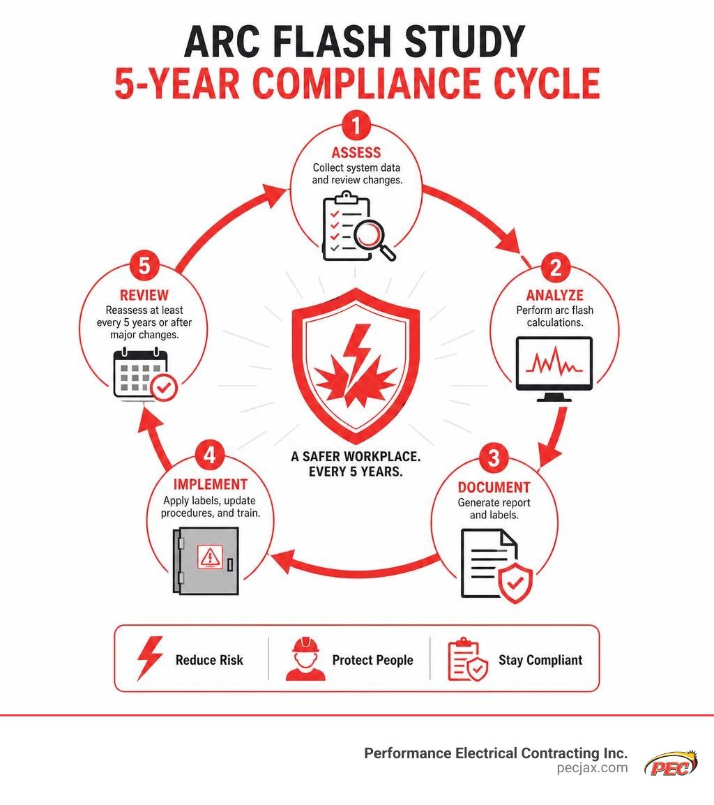
NFPA 70E mandates updating the arc flash analysis at least every five years, or whenever major facility modifications occur. The study yields site-specific labels applied directly to electrical equipment, displaying:
- Calculated Incident Energy (in cal/cm²)
- Arc Flash Protection Boundary distance
- Nominal System Voltage
- Required Minimum PPE Category
If you are unsure whether your electrical infrastructure meets current standards, consider How to Tell When Your Home Needs an Electrical Safety Inspection to establish an accurate baseline.
Balancing Arc Flash Mitigation with System Selective Coordination
A common engineering challenge when installing fast-acting mitigation devices is preserving selective coordination. Selective coordination ensures that during a downstream fault, only the immediate protective device clears the fault, preventing upstream breakers from tripping and shutting down entire facilities.
(In a coordinated system, ONLY the Branch Breaker trips, keeping the rest of the facility powered.)
Setting circuit breakers to trip instantly shortens clearing times, but it can compromise selective coordination. Systems like maintenance mode switches solve this by letting personnel activate fast-tripping modes only during active maintenance window exposures. Once work is complete, technicians disengage the switch, restoring standard selective coordination for normal operations.
Frequently Asked Questions about Arc Flash Mitigation
What is the primary difference between active and passive arc flash mitigation?
Active mitigation relies on sensors and controls (like light relays or pyrotechnic quenching units) that detect a fault and take immediate action to clear or extinguish it in milliseconds. Passive mitigation uses physical structures (like arc-resistant enclosures, remote racking tools, or IR windows) that contain blast energy or keep personnel at a safe distance without altering fault duration.
How often must a facility update its arc flash study under NFPA 70E?
NFPA 70E requires reviewing and updating an arc flash study at least every five years. However, any significant modification to the electrical system—such as adding major transformer capacity, installing large motors, or reconfiguring protective relays—requires an immediate update to verify that label data remains accurate.
Why can lower arcing current in 480V systems result in higher incident energy?
In 480V low-voltage systems, arcing fault current drops to roughly 45–50% of the calculated 3-phase bolted fault current due to arc path impedance. Because standard overcurrent protective devices use inverse time-current curves (TCC), this reduced current level can cause protective devices to take significantly longer to trip. The extended duration dramatically increases total incident energy compared to higher-current faults that trip instantaneously.
Modernize Your Electrical Safety Strategy Today
Selecting and implementing the right arc flash mitigation solutions requires balancing personnel protection, system reliability, and regulatory compliance. At Performance Electrical Contracting Inc., our experienced team delivers end-to-end commercial electrical services across Jacksonville, FL, and the Southeast U.S. From risk assessments and infrastructure upgrades to active protection retrofits, we deliver value-driven solutions that keep your systems operating safely.
Ready to lower incident energy levels, protect your workforce, and streamline compliance? Explore our comprehensive Commercial Electrical Contracting Services today to partner with our team on your next safety upgrade.